Requirements
- 3+ LEDs with current limited using resistors, at least one of which fades
- button, tilt switch, or custom switch with current limited
- for-loop
- digitalWrite()
- digitalRead()
- analogWrite()
Schematic
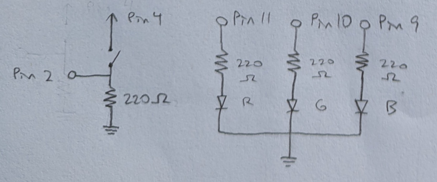
Each diode and switch is wired to its own pin providing power.
The 3 diodes all connect to the same ground.
The calculation below yielded the minimum resistances needed.
Calculation
Red and Green LEDs:

Blue LED:

Pushbutton:
Pushbuttons were rated for 50mA on the datasheets (octopart).

220 Ohm resistors were used for all 4 resistors across 3 different situations.
- For red and green, it was the closest resistor value which exceeded the minimum of 160.
- For blue, the minimum was 100, but I would not use exactly 100, since fluctuations could cause the necessary resistance to actually be more than 100 at times. Thus 220 was the next smallest value available.
- For the button, the minimum was 85, but 220 still worked fine, and if I used it then I would have less risk of mixing up resistors later, since all my resistors would be the same, so I chose to use 220 for the button as well.
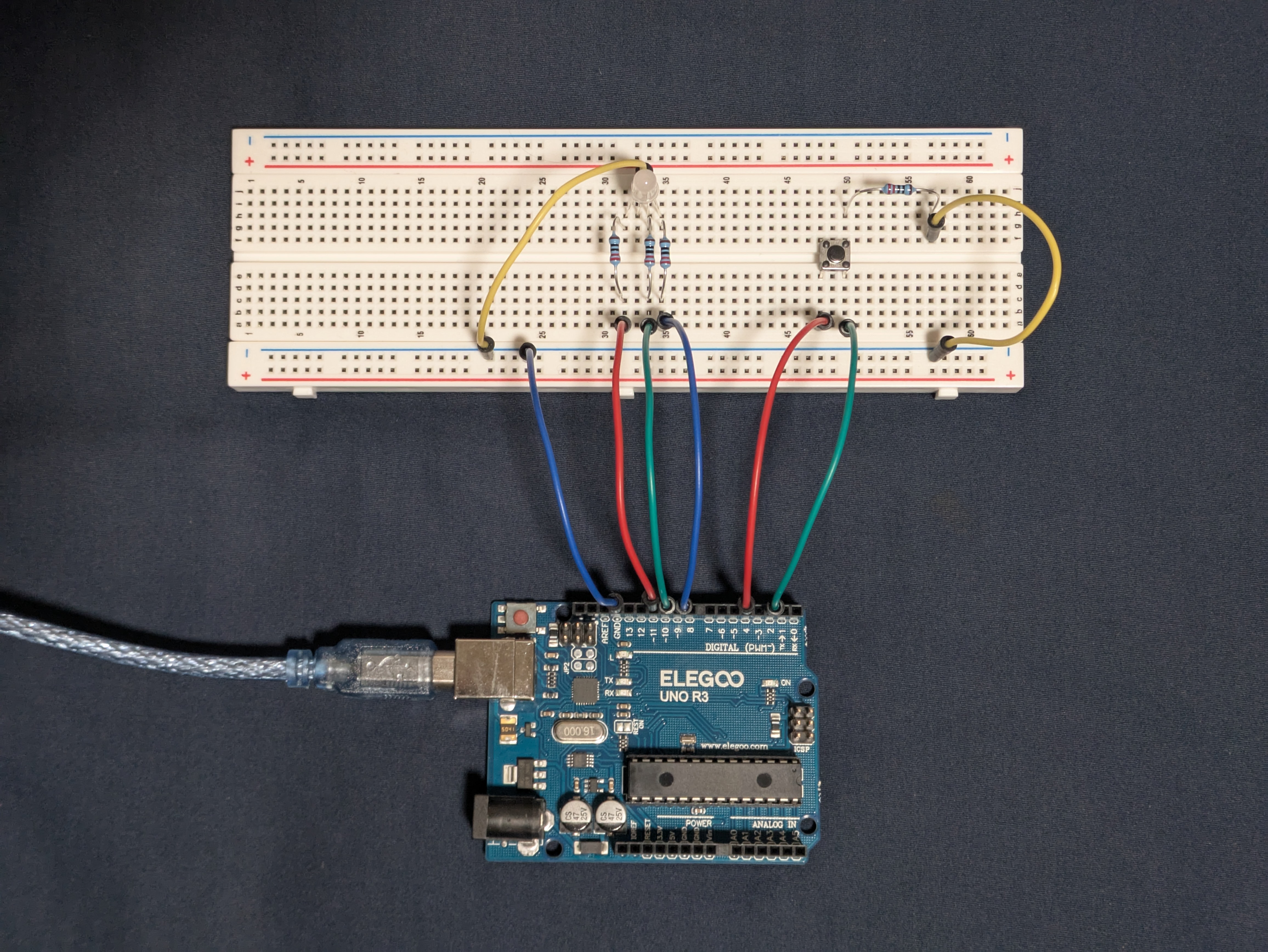
Circuit
Firmware
link to code file
/*
  Fade

  Built with Examples/02.Digital/Debounce and Examples/03.Analog/Fading

  Pushbutton toggles to fade 3 LEDs in or out.

  The LEDs are attached to pins 9, 10, and 11.
  The pushbutton is connected to power through pin 4 and input through pin 2.

  modified 13 Oct 2025
  by Heidi Wang
*/

// the number of the pushbutton pin
const int buttonPin = 2;
// the number of the pin for LED 1
const int ledPinR = 9;
// the number of the pin for LED 2
const int ledPinG = 10;
// the number of the pin for LED 3
const int ledPinB = 11;

// the current state of the output pin
int ledState = HIGH;
// the current reading from the input pin
int buttonState;
// the previous reading from the input pin
int lastButtonState = LOW;

// the last time the output pin was toggled
unsigned long lastDebounceTime = 0;
// the debounce time; increase if the output flickers
unsigned long debounceDelay = 50;

// the setup function runs once when you press reset or power the board
void setup() {
  // initialize the button pin as an input
  pinMode(buttonPin, INPUT);
  // initialize the pin for LED 1 as an output
  pinMode(ledPinR, OUTPUT);
  // initialize the pin for LED 2 as an output
  pinMode(ledPinG, OUTPUT);
  // initialize the pin for LED 3 as an output
  pinMode(ledPinB, OUTPUT);

  // initialize the pin for button power as an output
  pinMode(4, OUTPUT);
  // set voltage to HIGH to provide power to the button
  digitalWrite(4, HIGH);

  // set initial state for LED 1
  digitalWrite(ledPinR, ledState);
  // set initial state for LED 2
  digitalWrite(ledPinG, ledState);
  // set initial state for LED 3
  digitalWrite(ledPinB, ledState);
}

// the loop function runs over and over again forever
void loop() {
  // read the state of the switch into a local variable:
  int reading = digitalRead(buttonPin);

  // check to see if you just pressed the button
  // (i.e. the input went from LOW to HIGH), and you've waited long enough
  // since the last press to ignore any noise:

  // If the switch changed, due to noise or pressing:
  if (reading != lastButtonState) {
    // reset the debouncing timer
    lastDebounceTime = millis();
  }

  // check whether the reading has been there for longer than the debounce delay
  if ((millis() - lastDebounceTime) > debounceDelay) {
    // whatever the reading is at, it's been there for longer than the debounce
    // delay, so take it as the actual current state:

    // if the button state has changed:
    if (reading != buttonState) {
      // take the reading as the actual current state
      buttonState = reading;

      // only toggle the LED if the new button state is HIGH
      if (buttonState == HIGH) {
        // toggle the LED
        ledState = !ledState;

        // if the new LED state is HIGH, then fade the LED on
        if (ledState == HIGH) {
          // fade in from min to max in increments of 5 points:
          for (int fadeValue = 0; fadeValue <= 255; fadeValue += 5) {
            // sets the value for LED 1 (range from 0 to 255):
            analogWrite(ledPinR, fadeValue);
            // sets the value for LED 2 (range from 0 to 255):
            analogWrite(ledPinG, fadeValue);
            // sets the value for LED 3 (range from 0 to 255):
            analogWrite(ledPinB, fadeValue);
            // wait for 30 milliseconds to see the fading effect
            delay(30);
          }
        }
        // else the new LED state is LOW, then fade the LED off
        else {
          // fade out from max to min in increments of 5 points:
          for (int fadeValue = 255; fadeValue >= 0; fadeValue -= 5) {
            // sets the value for LED 1 (range from 0 to 255):
            analogWrite(ledPinR, fadeValue);
            // sets the value for LED 2 (range from 0 to 255):
            analogWrite(ledPinG, fadeValue);
            // sets the value for LED 3 (range from 0 to 255):
            analogWrite(ledPinB, fadeValue);
            // wait for 30 milliseconds to see the fading effect
            delay(30);
          }
        }
      }
    }
  }

  // save the reading. Next time through the loop, it'll be the lastButtonState:
  lastButtonState = reading;
}
Operation
Questions
-
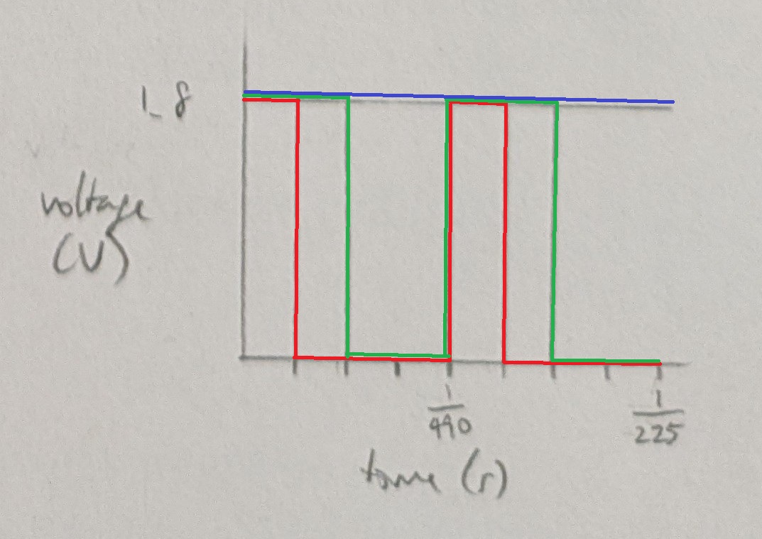
The voltage is assumed to be across an LED with a 1.8V drop.
Voltage over time for analogWrite with 3 duty cycles
Red = 64, Green = 128, Blue = 255
-
With 3 LEDs that draw 20mA of current each, i.e. 60 total in parallel, a 1200mAh battery can power the circuit for 1200mAh / 60mA = 20 hours.
-
The voltage across my 3 LEDs when all were on was: R 1.96 G 2.67 B 2.66V. The theoretical voltage drop for R and G is 1.8V, while for B is 3.3V. The actual voltage across was greater for R and G and less for B.
-
No AI use.